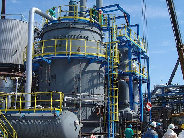
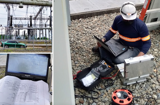
The major equipment for this modification consisted of Reactor and Salt Heater on anhydride plant. Both equipment were handling hazardous material. Thus the environment around the major equipment was determined and found to be Class 1 Div 2.

The electrical system was designed accordingly as per codes for classified hazardous area. Due to large motor load of the Reactor Motor and poor power factor. Soft Starter was added to inhibit the starting inrush current and capacitor were added to mitigate the power factor.
In addition to the two major equipment there were number of other pumps that required Variable Frequency Drives to regulate the speed. The client purchased the electrical equipment from Germany marketplace. That presented some challenges in understanding the drawing prepared in German standard.The other challenge was to interface the German standard connections to the equipment in conformance with Canadian Standards and as per Canadian Codes.
The electrical distribution system was existing. The power from existing switchboard in the vicinity was available. However, the load calculations were required to establish the spare capacity, based on the availability we could either use all the additional power needed from this switchboard or look for other sources of power. The load calculation determined that the switchboard with the given demand and diversity factor can handle the addition of new Reactor system load. However, this will push the capacity of the switchboard to its maximum capacity, leaving no room for any other future load. The client was informed of the limitation and they were in agreement with our recommendations.

Two branch breakers 1000A and 600A suitable for the existing switchboard were needed to tap power. The 600A breaker was to feed the single load of the New Reactor 300 HP motor. New 1000A Motor Control Center was installed to feed the 10 feeds that were needed for Salt Water Heater elements and to feed other miscellaneous loads. Four (4) of the ten Heating elements required variable control of heat for which Thyristors were installed.
Most of the power was distributed by using Armored Teck Cables in cable trays. Voltage drop Calculations were made both for power and Instrumentation cables due to long runs. Overall the project went well and was completed to the satisfaction of the client.

The electrical system was designed accordingly as per codes for classified hazardous area. Due to large motor load of the Reactor Motor and poor power factor. Soft Starter was added to inhibit the starting inrush current and capacitor were added to mitigate the power factor.
In addition to the two major equipment there were number of other pumps that required Variable Frequency Drives to regulate the speed. The client purchased the electrical equipment from Germany marketplace. That presented some challenges in understanding the drawing prepared in German standard.The other challenge was to interface the German standard connections to the equipment in conformance with Canadian Standards and as per Canadian Codes.
The electrical distribution system was existing. The power from existing switchboard in the vicinity was available. However, the load calculations were required to establish the spare capacity, based on the availability we could either use all the additional power needed from this switchboard or look for other sources of power. The load calculation determined that the switchboard with the given demand and diversity factor can handle the addition of new Reactor system load. However, this will push the capacity of the switchboard to its maximum capacity, leaving no room for any other future load. The client was informed of the limitation and they were in agreement with our recommendations.

Two branch breakers 1000A and 600A suitable for the existing switchboard were needed to tap power. The 600A breaker was to feed the single load of the New Reactor 300 HP motor. New 1000A Motor Control Center was installed to feed the 10 feeds that were needed for Salt Water Heater elements and to feed other miscellaneous loads. Four (4) of the ten Heating elements required variable control of heat for which Thyristors were installed.
Most of the power was distributed by using Armored Teck Cables in cable trays. Voltage drop Calculations were made both for power and Instrumentation cables due to long runs. Overall the project went well and was completed to the satisfaction of the client.
Comments
Post a Comment